Studer A62 Tape Machine
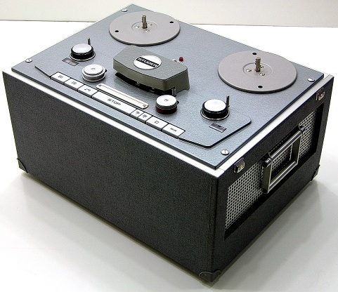
Studer A62 Tape Machine (Operating and Service Manual)
The Tape Recorder STUDER A62 exhibits the following design features:
- Fully up to date transistorised plug-in electronics
- Plug-in equalisers
- Interchangeable head-blocks
- Light weight and small dimensions
- Simple to operate, all functions can be remote controlled
- Mounting position: anything from horizontal to vertical
The interchangeable sub-assemblies allow this machine to be quickly adapted to all the requirements of modern mono and stereo recording. Its small dimensions and the light weight make the STUDER A62 eminently suitable for mobile use and in confined spaces. Great care in manufacture and in testing ensure a high standard of quality in every STUDER A62.
MECHANICAL CONSTRUCTION
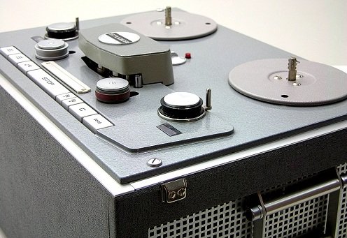
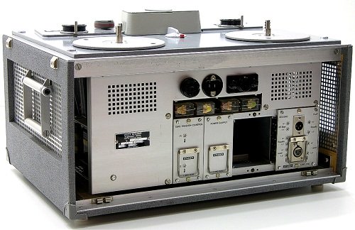
The entire tape transport mechanism is held together by the cast aliminium deck plate. The spooling deck and the capstan deck are screwed onto it. The spooling deck contains the spooling motors and brakes and the entire mains section and the magnetic amplifier for the tape tension control. The capstan deck contains the capstan motor, pressure roller and the tape guides. The control buttons for the tape transport, the headblock and the timing indicator are also part of this sub-assembly.
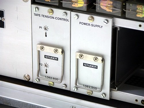
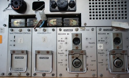
The amplifier frame houses the plug-in amplifiers, the stabiliser and the tape tension control amplifier.
DECK PLATE
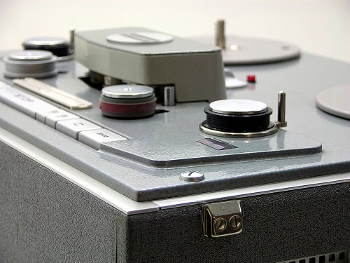
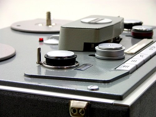
The two tape tension arms (jockey arms) with their associated damping pistons are built into the deckplate. All other tape guide elements are mounted on the capstan deck. These jockey arms serve the purpose of smoothing transitory changes in tape tension which occur when starting the tape and due to splices going through.
The piston damping of the jockey arms can be adjusted from the top of the deckplate. The adjustment for the spring tension becomes accessible by removing the tape guide rollers.
HEADBLOCK
The headblock is an aluminium casting which is screwed to the capstan deck, resting on it in three points. All connections are made via a 24 pole AMPHENOL plug. They are sufficient spare contacts for stereo headblocks and special versions with pilot tone, etc.
To avoid pick-up of stray magnetic fields, the record and playback heads are provided with Mu-metal screening cans. To maintain the height of the tape accurately, special tape guides with wear resistant guide discs are fitted before the erase head and behind the playback head. The Internal width of the tape guides is 6.3 mm (.248") corresponding with the standard tape width.
The fixing screws of the headblock and the adjustment screws for the heads are accessible by lifting off the cover plate .Behinde the erase head Is also the tuning capacitor for the erase oscillator. Only this capacitor should be altered when adjusting the oscillator frequency. The frequency should be set to 80 kc/s + 300 / - 0 c/s (MONO).
In the stereo headblock the printed circuit card contains one capacitor for every channel. Another difference from the mono version is that there are no wire links.
RECORD AMPLIFIER
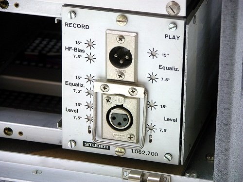
The record amplifier is housed in the same plug-in unit as the playback amplifier. Looking at it from the front-plate, the record amplifier is on the left printed circuit plate ("Record" ). The upper CANNON connector (XLR-3-32) is the input to the record amplifier.
The record printed circuit card contains a balanced input transformer, plug-in equalisers, three plug-in relays:
RLA Siemens Trls 162 b 65.4.21 / 119 e Switching of equalisation and
switching of 7.5 ips/15 ips
RLAO Siemens Trls 162 a 65.422 / 119 d bias
RA Siemens Trls 162 a 65.422 / 119 d Oscillator
and the record amplifier itself and the Oscillator.
PLAYBACK AMPLIFIER
The playback amplifier is housed in the same cassette as the record amplifier. Looked at from the front plate the playback amplifier is on the right-hand printed circuit card (PLAY). The lower CANNON connector (XLR-3-31) is the output of the playback amplifer.
The playback printed circuit card contains a balanced output transformer, plug-in equaliser units and a relay for switching the equalisation :
RLW Siemens Trls 162 b 65.421 / 119e for switching the equalisation.
The amplifier has two sections, the playback amplifier with plug-in equalisation and the line amplifier.
The output from the playback head goes to a three stage direct coupled playback amplifier. The equalisation is switched automatically by means of the relay RLW to the tape speed in use.
OSCILLATOR
The push-pull oscillator is switched click free by means of a switching transistor. The switching transistor is controlled by the trigger voltage from the relay RA, the switching-on time constant being controlled by the resistor R26 and the electrolytic condenser C16. The output of the oscillator is coupled to the tuned circuit L3/C14.
Tthe headblock and the plug-in amplifier units can be interchanged without affecting the oscillator frequencies. The oscillator frequency is 80 kc/s. The frequency should be adjusted when the machine is cold to a tolerance of + 300 c/s; -0 c/s (MONO). With stereo and two track operation the oscillators synchronise via the coupling in the erase head. When adjusting the oscillator frequency both channels should be adjusted separately to the same frequency. Note: The individual frequencies are higher than the nominal frequency as the effective frequency is reduced due to the coupling in the erase head.
Foundational tex courtesy of Studer.
Studer A62 Tape Machine
Do you have content, to add, about the Studer A62 Tape Machine or associated topics? Please feel free to Share it, here!
Return from Studer A62 Tape Machine to Magnetic Tape Recorders and Reproducers Return from Studer A62 Tape Machine to History of Recording - Homepage |
