Tektronix 2215A Oscilloscope
Tektronix 2215A Oscilloscope (Instruction/Service Manual)
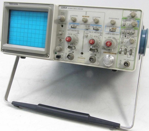
The TEKTRONIX 2215A Oscilloscope is a rugged, light weight, dual-channel, 60-MHz instrument that features a tiright, sharply defined trace on an 80- by 100-mm cathode ray tube (crt). Its vertical system provides calibrated deflection factors from 2 mV per division to 5 V per division. Trigger circuits enable stable triggering over the full bandwidth of the vertical system. The horizontal system provides calibrated sweep speeds from 0.5 s per division to 50 ns per division along with delayed-sweep features. A X10 magnifier circuit extends the maximum sweep speed to 5 ns per division when the A and B SEC/DIV switch is set to 0.05 iis per division.
Signals to be displayed on the crt are applied to either tine CH 1 OR X input connector or the CH 2 OR Y input connector. These signals may be directly (DC) coupled to the Attenuator circuit or ac (AC) coupled through an input-coupling capacitor. The input signals may also be disconnected from the oscilloscope circuitry and the input attenuator grounded by setting the coupling switch to the GND position.
The output signal from the Attenuator circuit is applied to the Vertical Preamplifier for further amplification. Additionally, the Channel 2 Attenuator can invert the Channel 2 display on the crt. Trigger Pickoff Amplifiers in each channel supply an internal trigger signal from either or both channels to the Internal Trigger Amplifier.
Input signals are selected for display by the Channel Switching circuit under control of the front-panel VERTICAL MODE switches. The output signal from the Channel Switching circuit is applied to the Delay Line Driver stage. This stage converts a current input to a voltage output and provides an impedance match for the Delay Line. The Delay Line produces approximately 90 ns of delay in the vertical signal. This allows the Horizontal circuitry time to start the sweep so that the operator can see the signal that triggered the sweep.
Final amplification of the vertical signal is performed by the Vertical Output Amplifier. This Amplifier supplies the signal levels necessary for vertical deflection of the electron beam in the crt. The upper frequency response of the Amplifier can be reduced by enabling the Bandwidth Limit circuitry. For locating the position of off-screen displays, the dynamic range of the Amplifier can be limited with the Beam Find circuitry. This circuitry also intensifies the trace and limits horizontal deflection.
Tektronix 2215A Oscilloscope
Do you have content, to add, about the Tektronix 2215A Oscilloscope or associated topics? Please feel free to Share it, here!
Return from Tektronix 2215A Oscilloscope to Test and Measurement Equipment Return from Tektronix 2215A Oscilloscope to History of Recording - Homepage |

