MCI JH-500 Series Console
Message Board - MCI JH-500 Series Console
MCI introduced the JH-500 Series consoles in 1976 as the most flexible consoles ever built. This is the console which is now leading the Professional Recording Industry into the age of Automation. The basic design incorporates Voltage Controlled Amplifiers (VCAs) in all the important circuit positions which need to be automated. Automation controls are already built into the panels of each JH-500 console. Thus no design changes are needed when Automation is added.
The JH-500 Consoles were designed from the start with the idea that this was to be the most advanced, the most adaptable mixing system that our present technology-could build. Every advanced technique was used—regardless of cost. Every desirable feature agreed on by the industry was incorporated—regardless of the engineering difficulties.
HEAD ROOM
One of the most important features of the JH-500 Console is its increased HEAD ROOM. MCI has designed this console to supply enough dynamic range for those who are experimenting with Digital Recording systems (80db to 90db dynamic range is predicted). Thus the HEAD ROOM is more than adequate for normal recording levels of +4db or elevated levels of +6db or +8db. There is a MINIMUM of 24db Head Room (above a +4db level) at all points in the console. The microphone preamp circuit has 34 db Head Room above its nominal level of -6db. This extended Head Room assures the studio that there will be no increased distortion when levels are high and that intermodulation distortion will be low at all times.
INPUT/OUTPUT MODULE
The JH-500 is an IN-LINE console. All of the circuits needed for one complete MICROPHONE CHANNEL and one complete REMIX CHANNEL are contained in a single I/O module. Any number of I/O modules may be purchased—up to the maximum for each of the three frame sizes available. If additional channels are needed, they may be added simply by plugging in new I/O modules.
OUTPUT BUSES
The thirty-two channel buses are constructed so as to take advantage of the excellent common mode rejection of modern opamps. The output of each I/O module is bused as a differential voltage and summed with the output of other I/O modules by a Differential Active Combining Network. Any RF, hum, or noise pickup in the bus structure is seen as COMMON MODE by the summing op-amp and is therefore rejected. This design achieves a wide-band "noise floor" as much as 20db lower than many competitive consoles.
MUTES
Muting is accomplished by shorting the signal line to ground through a relay contact. This system keeps the "noise floor" at the lowest possible level by removing all of the preceding circuit noise as well as the audio signal. In addition to the CHANNEL MUTE button, all Channel, Group, and Master Faders have a switch at the minimum gain end to activate the appropriate mute. When the console is automated, the VCA and the Mute relay work together to provide a musically pleasing 40ms ramped "kill" to the noise floor followed by the relay action. When the channel is unmuted, the relay contact release is followed by a VCA ramp to the Fader level.
CUE SYSTEM
Two stereo Cue systems are provided. These systems may be fed from the Stereo Mix buses, the Sends, the Echo Returns, from any external source, or from a combination of any of these sources. The six SEND buses may also be used as additional CUE SENDS during taping sessions when Echo Sends are not needed. This arrangement allows great flexibility in feeding a specific channel or group of channels (such as the rythm, or the vocal) into a Cue line, to be summed with the complete Stereo Mix at a lower level to produce a Cue signal tailored to the use of a particular musician. Several of these special Cue lines can be mixed at the same time. Stereo panning of the Echo Returns into the Cue lines adds realism to the Cue mix.
EQUALIZATION
MCl's precision EQ circuits may be used either in the Channel or in the Monitor. They are carefully designed to musical scales, not to mathematical relationships. The switch positions define exact sound control points which are easy to find and easy to recapture or to reproduce on another module. Instead of the usual Variable gain—fixed "Q" circuits which change the tonal value as the amplitude is adjusted; MCI has designed Variable gain—variable "Q" circuits to maintain the tonal balance as the amplitude is adjusted. The BANDPASS of each circuit remains relatively constant so that when the EQ is boosted or cut, the slope of the curve increases to emphasize QNLY the sound you are looking for. Thus you do not need to use excessive EQ to achieve the effects you want. With over 140 million combinations to choose from, you can create the EXACT sound you want with all of the dramatic impact that you wish to use.
METERS
MCl's PLASMA DISPLAY system provides a new dimension in audio metering. It uses a 10O segment NEON GLOWTUBE to produce a lighted BAR GRAPH of the audio level. Cardinal scale markings on the Graph are shown by brighter bars. This unique scale marking system is produced by PROMs (Programmable Read Only Memories) in a different pattern for each mode of operation. Each Bar Graph is scanned (Refreshed) over 40 times a second for a highly readable, flicker-free display. Lighted scale numbers appear beside each Graph, providing quick identification of the scale being used and the values of the scale markings. Since the scale is divided into 100 divisions, it is possible to achieve remarkable resolution in the upper, expanded portion of the scales. Accuracy is better than +0.2db from -10db to full scale. The dynamic range of PEAK mode is 50 db, of VU mode is 36 db.
The PLASMA DISPLAY offers three modes of operation, VU, PEAK, and DC.
VU MODE: This scale has the familiar logarithmic markings. A 2-pole active filter adjusts the ballistics to ASA standard (matching the popular Triplett VU meter).
PEAK MODE:
This mode is displayed in db on a linear scale. The Rise Time and the Fall Time are individually adjustable over a range wide enough so that the meter can be set to match ANY ballistic standard. Normally, the factory adjusts the ballistics to DIN standard 45406, which is: Rise time = -20db to 0db in 10 ms. Fall time = 0db to -20db in 1.5 sec. The range of adjustment possible in this mode is: Rise Time — 2ms to 20ms Fall Time — 0.5 sec. to 3 sec.
DC MODE:
This is the mode used with Automation to display VCA control voltage on each channel. This type of display has been found to be a very important part of the working Automation System. Its continuous display of the VCA control voltage on each channel (adjusted to include Group and Master Faders) supplies Fader level information which can be read at a glance. Softly-glowing LUMINESCENT PANELS are a standard feature of the PLASMA DISPLAY. They are both beautiful and useful. In addition to identifying the DISPLAY mode, they light up to show the modes of operation being used elsewhere in the console.
STANDARD VU METERS: can be supplied as a lower cost option.
AUTOMATION
JH-500 Series Consoles were designed and built to be completely Automation-ready. System controls and VCAs are already installed. The JH-50/500 Automation system can be installed at any time. The JH-50 System is MICROPROCESSOR-based. During MIXDOWN, it scans all of the FADER and MUTE functions (Plus Grouping and any other automated functions) at the rate of 9.8 times per second and records their levels. As the sound Engineer adjusts channel levels to achieve the best MIX, the Automation faithfully follows each change. Data accumulated by the Automation system is normally recorded on two unused tracks of the multitrack tape. Tape tracks are used in A—B—A—B—A sequence as UPDATES are made during Mixdown. A switching matrix is provided to control as many as 4 tracks for Data recording and playback.
All control movements are so simple that anyone capable of mastering the art of mixing a Multitrack tape is capable of operating an Automated Console after only a few minutes of instruction. Three buttons (VCA WRT, VCA UPDT, & MUTE WRT) control the MODE SWITCHING for the entire-console. An identical set of buttons is available for controlling each Group when a change is to be made on a Group of modules. Each I/O module, and each Echo Return circuit has its set of three buttons for use when ONLY that one circuit needs changing. All sets of buttons work alike, so the Engineer has to learn to operate ONLY THREE BUTTONS.
A single button stroke switches the whole console or any section thereof to WRITE mode, or to UPDATE mode. A single button stroke switches from WRITE or UPDATE mode back to READ mode. The complex manipulations needed to ensure a smooth transition between one mode and the next, between an old Data track and the new Updated track, are made AUTOMATICALLY by the MICROPROCESSOR:
NULLING: WHEN ENTERING UPDATE MODE the MICROPROCESSOR puts into memory the physical position of the Fader and equates that position to the Fader level being READ from the previous Data Track. UPDATES are recorded as the CHANGES made from the position of the Fader when UPDATE mode was initiated. This means that BEFORE GOING INTO UPDATE MODE, you may set your Faders to ANY POINT YOU WISH, and your MIX will be UPDATED smoothly by any movements you make. You may use the upper—fine control—section of the Fader if you wish to make delicate adjustments. OR you may use the lower—coarse control—section of the Fader if you wish to make sweeping corrections. WHEN LEAVING REWRITE MODE OR UPDATE MODE the MICROPROCESSOR automatically shifts into a temporary mode which allows the mode shift to occur ONLY when the levels are matched with
the level in READ mode. You may override this automatic nulling circuit IF YOU WISH TO MAKE A STEP CHANGE IN LEVEL by an extra button stroke. Thus NO MANUAL NULLING IS REQUIRED. With MCI Automation, you mix with your ears, not with null indicators.
MUTING
When a MUTE is recorded, the Fader level is stored and kept as part of the recorded Data track. Thus, if you ever wish to UNMUTE the channel, the Fader will return to the level it had before the channel was MUTED.
DELAYS
The accumulatable DELAYTIME for the JH-50 System is 1.2 milliseconds per UPDATE PASS. This tiny delay is the same whether you make a single change, or 100 changes on one pass. The NUMBER of changes being made AT THE SAME TIME does not increase the delay. The total DELAYTIME accumulated while working out a Mix is 1.2ms multiplied by the number of times you rewrite the Data Track. (READ mode passes do not rewrite the Data Track). You may listen to your Mix as many times as you wish without adding any delay.
The average human reaction time between hearing and moving is about 200 milliseconds. You could make 160 UPDATE passes while working on a Mix before the total accumulated delay is 200ms. Many Engineers are finding the JH-50 Automation so easy to use that they make their first Mix during a final taping session. The Data Track from this mix becomes the working Mix which they use to start their mixdown session.
When the Automation Power supply is turned OFF, FET switches automatically switch all controls back to the same functions they had in an UNAUTOMATED console. It is YOUR choice; with the Automation Power Supply ON, you can make an AUTOMATED MIX. With the Automation Power Supply OFF, you can use your console as if it were not Automated.
PATCH BAY FACILITIES
All of the Patch Points except the Microphone Preamp output are at the standard level of +4db. (The MICROPHONE PREAMP OUTPUT is at -6db). This unusual standardization of level is the result of the extended headroom availablein this console. Having the same level available from all Patch points makes it easy to interface with all other Control Room equipment.
TIE LINES
(84 lines in the standard JH-528 Console).
(160 lines in the standard JH-532 Console).
(132 lines in the standard JH-536 Console).
(218 lines in the standard JH-538 Console).
(176 lines in the standard JH-542 Console).
OPTIONS
JH-35 SPECTRA VUE
This option separates a Mix, or a Solo, into twenty-one 1/2 octave bands and displays the content of each band on a separate console meter. This AUDIO SPECTRUM ANALYSIS is made in "real time" so that you may see and hear your mix at the same time.
VCA-DC STATUS DISPLAY
This plug-in module adds the DC mode to any Plasma Display. It is particularly useful during Automated Mixdown operations.
JH-22 PHASE METER
This meter provides a quick and accurate Phase comparison between any two Audio Signals. It reads directly in degrees, providing a ± 180 degree scale.
"SEND" VU METERS
These six meters are vertical display (1/2 in. wide, 1 1/2 in. high). (They are used with Plasma Display Consoles only).
ECHO RETURN AUXILIARY MODULE
This module contains 4 additional Echo Returns which feed into the Quad Mix Buses.
EQUALIZER AUXILIARY MODULE
This module contains 4 complete EQ systems similar to the EQ circuits in the I/O modules. Input is lOk Ohms. Output is 600 ohms.
FADER WRITING STRIPS
Two types of Writing strips are available. One is plastic and mounts above the Linear Fader. The second type is designed to hold 1 inch paper tape and mounts either above or below the Fader.
MICROPHONE PATCHBAY
A "normalized" microphone input patch point is installed for each I/0 module.
ADDITIONAL TIE LINES
All Consoles can be supplied with additional tie lines installed in the Patch Bay. The additional lines available for each console are: JH-528 = 56, JH-532 = 72, JH-542 = 84.
PRODUCER'S DESKS
The standard Desk matches the JH-500 Console and bolts to the console on either the right end or the left end. Stereo power amplifiers and speakers are mounted into a panel which matches either the VU or the LM meter houseing. Twelve (12) remote function control switches are installed and recessed space for mounting a standard commercial turntable is provided. (Turntable not provided by MCI). Another line of matching desks is available which provides mounting room for auxiliary equipment.
Photos and foundational text courtesy of Larry Lamoray and Carla Harned, of MCI.

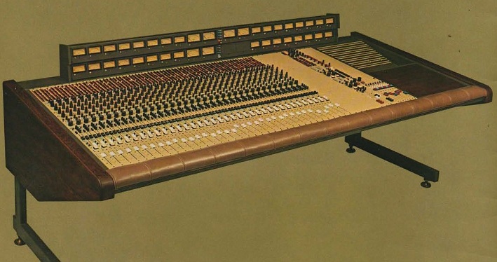
MCI JH-528 Recording Console. Photo courtesy of Larry Lamoray and Carla Harned, of MCI.

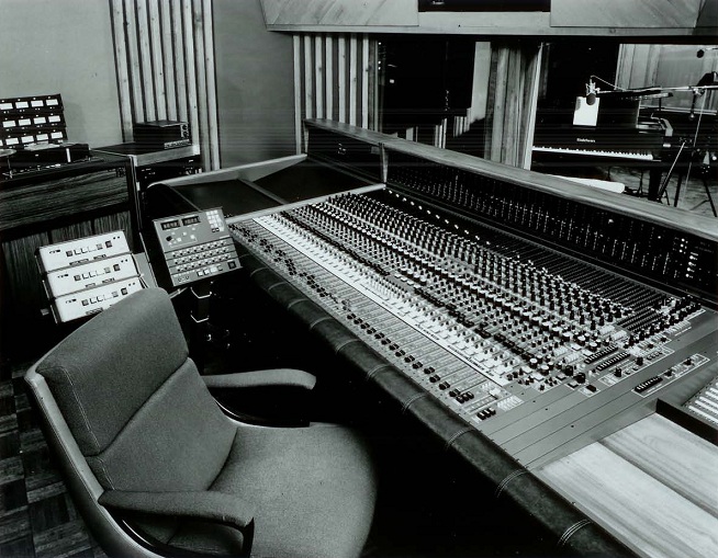
MCI JH-538D Console at Charley Pride's Cecca Sound Studios, Dallas Texas. Photo courtesy of Larry Lamoray and Carla Harned, of MCI.

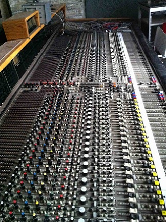
MCI JH-556 Series Recording Console. Unknown owner.

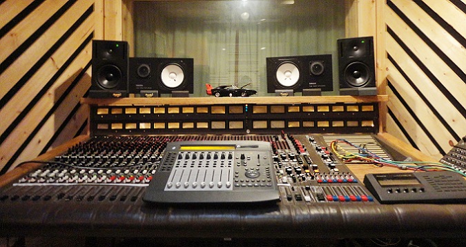
MCI JH-528C Recording Console at Silo Sound Studios. Photo courtesy of Larry Lamoray and Carla Harned, of MCI and Silo Sound Studios.
MCI JH-500 Series Console
Do you have content, to add, about the MCI JH-500 Series Console or associated topics? Please feel free to Share it, here!
What other Visitors have said about the MCI JH-500 Series Console
Click below to see contributions from other visitors to this page...
Additional to Plasma meters 


The origins of the plasma meters come from CBS London who gave MCI an NTP plasma meter and said, "This, all along the console, please." The meters originally …
MCI JH-500 Recording Console at Arte Nova Music Lab Bogota Colombia 


Arte Nova Music Lab is one of the main outstanding schools of Audio, Music and Music Production in Colombia. The MCI JH-500 Series Console is the "treasure" …
Burro Not rated yet
JH are the initials of Jeep Harned, the founder.
Early boards used only one set of sliders for BOTH record and playback, by using the tape recorder …
MD at STC Studio Denmark Not rated yet
The MCI 500 from CBS London.
Svend Christiansen
Probably the best sounding console ever produced by humans. Not rated yet
I bought my JH556-D LM because after figuring out which studio's and producers did the best sounding records ever, i also found out the consoles that have …
Another MCI JH500, in Argentina Not rated yet
Theres a very important studio in Argentina called Estudio Ion, which has a set of great gear, among a few, a MCI JH500.
cheers!
Gino Ivan
MCI JH-500 Recording Console at Arte Nova Music Lab Bogota Colombia Not rated yet
Arte Nova Music Lab is one of the main outstanding schools of Audio, Music and Music Production in Colombia.
The MCI JH-500 Series Console is the "treasure" …
Return from MCI JH-500 Series Console to Recording Consoles
Return from MCI JH-500 Series Console to History of Recording - Homepage |


